CAN (Controller Area Network) is a serial bus system that was developed for robust and fast communication in harsh environments like those realised in the automotive industry. The network is a multi-master network where all the devices attached to it receive the transmitted message and then decides if it is relevant. The hardware controller automatically retransmits messages that were interrupted due to data collision etc. Within this fault protection is also implemented a message priority so that messages with higher priority will be transmitted before those with a lower priority.
The CAN network is divided into layers. This starts with the physical layer (the network hardware connection). Then there are the higher layers (software) which implement the protocols that are application-specific. However, various standards have been developed - each aimed at a specific area. The J1939 and FMS standards are, for example, aimed for the automotive industry.
CAN messages all consist (from the user's point of view) of a message identifier (ID) and up to 8 data bytes. The ID is then divided into two groups: one with an 11-bit wide ID (CAN 2.0 A) called "standard identifier" and another with a 29-bit wide ID (CAN 2.0 B) called "extended identifier". Common for both types is the fact that the ID sets the message priority – the lowest ID has the highest priority.
As some nodes on the network communicate very often, there will be extensive traffic most of the time. Most of this information is not relevant, and in order not to handle irrelevant information the whole time, a need for filtering arises. The message is filtered based on the ID and is a hardware-realised filter - it discards all messages with an irrelevant ID.
The CAN implementation includes an optional logging mechanism which will automatically collect received CAN messages with a minimum of resource requirement - thus allowing a continuous collection of data while the device is performing other tasks.
The logging feature is independent and separate from the normal operations, which means that neither the logger nor the logging functions will affect sending or receiving messages normally. This means that the logging feature can be added to any application without changes to the existing code.
The filters are shared between normal operation and the logger, and as such, only the functions to create and destroy filters affect both.
The logger will ignore all new messages once it is full, so care should be taken to ensure that the logger data is moved to permanent storage at regular intervals to prevent this.
There is one logger for each CAN bus present on the device.
The following functions are used to access the CAN network.
Opens a CAN port. |
||
Closes a CAN port after use. |
||
Activates loopback mode for test purposes. |
||
Configure CAN as a wake-up source. |
||
Sends a CAN message. |
||
Receives a CAN message. |
||
Receives a CAN message, with timeout. |
||
Creates a receive filter. |
||
Creates a receive filter that only accepts one message. |
||
Creates a receive filter with advanced filter options. |
||
Destroys a receive filter. |
||
Gets status for receive filter. |
||
Clears all received messages. |
||
Returns the amount of buffer used. |
||
Configures logging feature. |
||
Starts logging received messages. |
||
Stops logging received messages. |
||
Returns the amount of space used by the logger. |
||
Reads the oldest message on the logger. (mode 1) |
||
Reads the oldest message on the logger. (mode 2) |
||
Moves the contents of the logger to memory. |
||
Creates a receive filter for a FMS/J1939 message. |
||
Extracts the FMS/J1939 PGN from a CAN message ID. |
The following functions are used to create a single connection to send and receive ISO-TP messages on:
Opens an ISO-TP connection via a CAN port. |
||
Closes an ISO-TP connection. |
||
Sends a message. |
The following functions are used to create multiple connections for sending and receiving ISO-TP messages:
Create an ISO-TP session. |
||
Closes the ISO-TP session. |
||
Sends a message via the ISO-TP session. |
CAN message ID
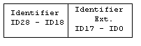
The CAN message identifier (ID) is represented as a DINT in VPL. As the CAN functions are common for both standard and extended identifiers, an illustration below shows how the bit is organized in the two cases.
The ID consist of either 11-bit (standard) or 29-bit (extended). The standard ID is always located ID28..18, and the extended ID is located in ID17..0. This is illustrated in (a).
a) CAN message ID:
For convenience in VPL, the standard identifier is shifted down - starting from zero (decimal) (b). Extended identifiers are then represented as they are received (c).
b) Std. ID presented in VPL:
![]()
c) Ext. ID presented in VPL:
![]()
CAN termination and Write enable
The CAN bus of the device should be properly terminated according to the CAN bus standard. For devices with hardware jumpers for termination and write enable the necessary information can be found in the technical manual and for devices with software controlled jumpers the function boardSwitchSet can be used.
The CAN implementation has the following limitations:
•There is a maximum of 30 filters available for each port.
•The internal buffer can hold up to 100 received CAN messages.