The GNSS functions allow the program to interact with a GNSS module that supports multiple positioning systems, such as GPS, GLONASS, and GALILEO. The GNSS functionality is not available on all RTCU devices, so please consult the technical documentation for the actual RTCU device in question.
The GNSS functions are to be used together with the GPS functions, where the GNSS functions handle the functionality for multiple positioning systems, while the GPS functions implicitly use all positioning systems.
Returns detailed information from the GNSS receiver. |
||
Accesses information about the satellites in view |
||
Returns information about GPS/GNSS features that are available on the RTCU device. |
||
Enables/disables the individual positioning systems. |
||
Read a bit mask of enabled positioning systems. |
||
Configure the dynamic model used by the GNSS module. |
Note: all values returned by the GNSS functions are in the WGS-84 datum.
To improve the performance in areas with poor or no signal conditions, some GNSS modules have support for Dead Reckoning using the following functions:
Return the status for Dead Reckoning. |
||
Enable or disable Dead Reckoning. |
||
Configure mounting vectors for the GNSS module. |
||
Configure the alignment(rotation) of the GNSS module. |
||
Configure support for Wheel Tick for using sensors in the vehicle to improve the performance. |
||
Send Wheel Tick data to the GNSS module. |
||
Send vehicle speed to the GNSS module. |
Dead Reckoning
Dead Reckoning allows for improved navigation performance in places with GNSS-denied conditions as well as during short GNSS outages.
It is based on Sensor Fusion Dead Reckoning (SFDR) technology, which integrates an Inertial Navigation System (INS) with GNSS measurements. The INS computes position, velocity and attitude changes and can, once initialized, provide accurate navigation information.
Two versions of the INS are used, one including WheelTick and one without WheelTick. These are traditionally called Automotive Dead Reckoning (ADR) and Untethered Dead Reckoning (UDR) respectively.
The GNSS uses some references to calculate the Dead Reckoning position:
The Vehicle Reference point (VRP) is the nominal point at which some motion constraints inherent to ground based vehicles are applied.
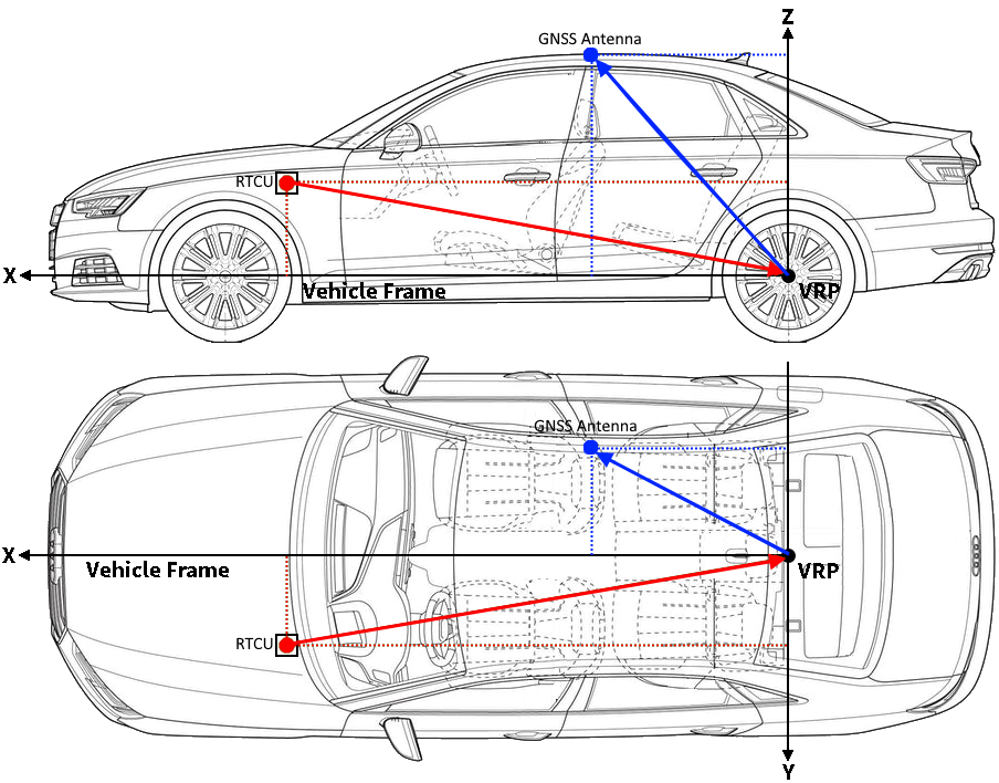
For automotive platforms, the VRP is defined as the center of the vehicle rear axle.
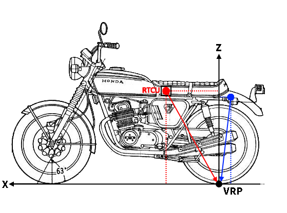
For bike platforms, the VRP is defined as the point where the wheel touches the ground. If the RTCU device is mounted on the handle bar, the VRP will be where the front wheel touches the ground, and if the RTCU device is mounted on the bike frame the VRP will be where the back wheel touches the ground.
The Device Frame is a right-handed 3D Cartesian frame connected to the RTCU device.
The x-axis points towards the back of the device (where the connectors and antenna connectors are present), the y-axis points towards the left of the device and the z-axis points up.
It is centered on the RTCU device.
The Vehicle Frame is a right-handed 3D Cartesian frame connected to the vehicle.
The x-axis points towards the front of the vehicle, the y-axis points towards the left of the vehicle and the z-axis completes the right-handed reference system by pointing up. It is centered on the RTCU device.
The alignment between the Device Frame and the Vehicle Frame can degrade the positioning solution (if small, typically a few degrees) or even prevent Dead Reckoning (if large, typically tens of degrees).
Therefore, it is important to correctly configure the alignment.
Normally the alignment is estimated during a dedicated initialization drive through an automatic alignment procedure.
For bike platforms, the automatic alignment procedure is not possible and the alignment must be set manually..
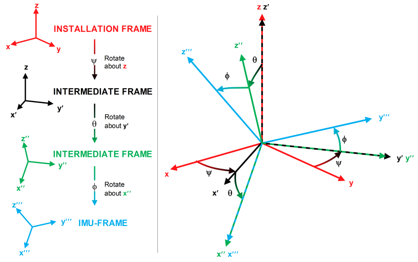
The alignment are the Euler angles required to rotate the Vehicle Frame to the Device Frame. The yaw rotation should be performed first, then the pitch and finally the roll. At each stage, the rotation is around the appropriate axis of the transformed Vehicle Frame, meaning that the order of the rotation sequence is important (see figure below).
The Vehicle Frame is also used when configuring the RTCU device mount relative to the VRP and the GNSS Antenna, as shown in the illustration below:
and on bike platforms: