Architecture: |
X32 / NX32 |
Device support: |
MX2 pro, DX4 pro, MX2 turbo |
Firmware version: |
1.11 |
The gsmModemMode function allows the use of the internal GSM module as a GSM modem. Using this mode will effectively "hand over" the GSM module inside the RTCU device so that it is exclusively controlled by any external device connected to serial port 1 on the device.
During the time where modem mode is enabled the GSM module will appear OFF to the VPL application and any attempt to turn the GSM module on by using the gsmPower function will return an error code. The GSM status LED will be inactive when gsmModemMode is active.
Before enabling modem mode, the GSM module must be powered on by using the gsmPower function, and when gsmModemMode returns, the GSM module will appear OFF and is therefore not accessible from the VPL application. When the modem mode is disabled again, the GSM module will resume normal operation as before the modem mode was enabled.
Controlling the GSM module from serial port 1 is with standard AT commands and detailed information about modem specific commands can be requested from Logic IO.
Warning:
Do not use the following AT commands: AT+IPR, AT+ICF, or AT&W.
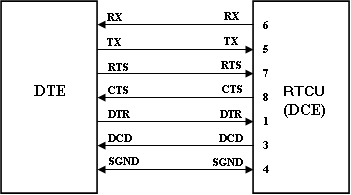
DCE Hardware Interface:
Serial port 1 is has been designed and documented as a DTE interface, and a modem is a DCE interface.
When entering Modem mode, serial port 2 changes therefore from DTE to DCE mode by using the following interface:
Pin # |
Signal |
1 |
DTR. |
2 |
Not used. |
3 |
DCD. |
4 |
SGND. |
5 |
TX. |
6 |
RX. |
7 |
RTS. |
8 |
CTS. |
The wiring for connecting a DTE device, such as a PC, to the device in Modem mode are as follows:
Please note that it is not allowed to change the modem speed with an AT modem command.
Input:
enable : BOOL
Will enable or disable the dedicated GSM modem mode.
baud : DINT (default: 9600)
The baud rate (bits per second) to use for communication with the GSM module over the serial port 1.
Valid values are: 9600, 19200, or 38400.
bit : SINT (default: 8)
Number of data-bits to use for communication with the GSM module over the serial port 1.
Valid values are: 7 or 8.
parity : SINT (default: 0)
The parity to use for communication with the GSM module over the serial port 1.
Valid values are: 0 (NONE), 1 (EVEN), or 2 (ODD).
stopbit : SINT (default: 1)
Number of stop-bits to use for communication with the GSM module over the serial port 1
Valid values are: 1 or 2.
Returns: INT
0 |
Operation was successful. |
1 |
GSM module not available. |
2 |
Serial port 1 is not present. |
3 |
Current processor speed is not supported. |
4 |
Invalid baud rate. |
5 |
Modem is active in a mobile network/CSD or VOICE session. |
6 |
Serial port 1 is in use. |
7 |
GSM module is not powered on. |
8 |
Function is only supported on the MX2 pro, DX4 pro and MX2 turbo. |
Declaration:
FUNCTION gsmModemMode : INT;
VAR_INPUT
enable : BOOL;
baud : DINT;
bit : SINT;
parity : SINT;
stopbit : SINT;
END_VAR;
Example:
INCLUDE rtcu.inc
VAR_INPUT
DI1 : BOOL;
END_VAR;
PROGRAM example;
VAR
rc : INT;
END_VAR;
BEGIN
...
IF DI1 THEN
// Enter modem mode, when input signal is high
rc := gsmModemMode(enable:=TRUE,baud:=19200);
...
ELSE
// Exit modem mode, when input signal is low
rc := gsmModemMode(enable:=FALSE);
...
END_IF;
END;
END_PROGRAM;