Architecture: |
X32 / NX32 / NX32L |
Device support: |
ALL |
Firmware version: |
1.00 / 1.00.00 |
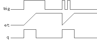
The TP function block is a pulse timer that enables "q" (the output) for a preset amount of time.
When trig is set TRUE, the "q" output is set TRUE and the elapsed time counter (et) is reset to zero and incremented until the preset timer value is reached, after which the "q" output is set FALSE.
Only during this period of time is "q" set to TRUE.
Once the timer is running, any changes to the trig input are ignored until after the preset value is reached.
This image shows the TP function block timing:
Input:
trig : BOOL (true/false)
On the leading edge of this input, the timer will start and set the "q" output true for the specified "pt" time
pt : DINT (0..2147483648)
Specifies how long the "q" output should be true - specified in ms.
Output:
et : DINT (0..2147483648)
The current value of the timer.
q : BOOL (true/false)
Output from the timer. This will go high until "et" equals "pt"
Declaration:
FUNCTION_BLOCK TP;
VAR_INPUT
trig : BOOL; | Leading edge on this signal will start the timer
pt : DINT; | Time where 'q' will be high after 'trig' signal
END_VAR;
VAR_OUTPUT
q : BOOL; | Output from timer
et : DINT; | Current timer value
END_VAR;
Example:
INCLUDE rtcu.inc
VAR_INPUT
input1 : BOOL; | Input that will enable the timer
END_VAR;
VAR_OUTPUT
signal : BOOL; | Output that will follow the q output from the timer.
END_VAR;
VAR
timer : TP; // Declare an instance of the TP functionblock
END_VAR;
PROGRAM test;
BEGIN
timer();
...
timer.pt := 100; // number of milliseconds the q output should be high
timer.trig := input1; // The timer will start on a leading edge on input1
signal := timer.q; // output will follow the q output from the timer
...
END;
END_PROGRAM;