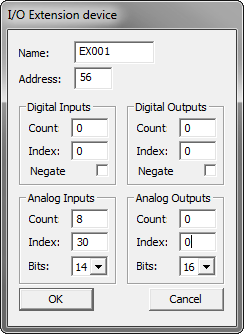
This dialog allows one to configure an I/O extension device.
Please consult the Technical Manual for the specific I/O Extension device for information about what parameters to use.
In all MODBUS I/O Extension devices delivered by Logic IO, there is detailed information on how to set up the module and what to enter in the set-up dialog.
Name:
This the name of the Device.
The name is used to identify the device in the Job configuration dialog, in the I/O monitor window, and in the Emulator.
The name is limited to 6 characters.
Address:
This is the address of the device. Each device on the net must have a unique address - all devices are delivered with address 1 by default.
Note: When changing the address, the new setting must be deployed to the device with Setup device.
Digital Inputs:
This is where the Digital Inputs are configured.
If there are no Digital Inputs in the device, set the parameters to 0 (zero).
Count:
This is the number of digital inputs on the device.
Index:
This is the index of the register used to read the state of the inputs. Only use this if the device does not support the "Read digital inputs" command.
Negate:
This option will negate the state of the digital inputs on the device.
Digital Outputs:
This is where the Digital Outputs are configured.
If there are no Digital Outputs in the device, set the parameters to 0 (zero).
Count:
This is the number of digital outputs on the device.
Index:
This is the index of the holding register used to set the state of the outputs. Only use this if the device does not support the "Write coils" command.
Negate:
This option will negate the state of the digital outputs on the device.
Analogue Inputs:
This is where the Analog Inputs are configured.
If there are no Analog Inputs in the device, set the parameters to 0 (zero).
Count:
This is the number of analog inputs on the device.
Index:
This is the index of the register used to read the state of the inputs.
Bits:
This is the number of bits used in the conversion.
This is used to give the correct range of values in the I/O monitor and the Emulator.
Analog Outputs:
This is where the Analog Outputs are configured.
If there are no Analog Outputs in the device, set the parameters to 0 (zero).
Count:
This is the number of analog outputs on the device.
Index:
This is the index of the holding register used to set the state of the outputs.
Bits:
This is the number of bits used in the conversion.
This is used to give the correct range of values in the I/O monitor and the Emulator.
Note:
It is possible to access holding registers by treating them as Analog inputs (to read) or Analog outputs (to write).