Architecture: |
NX32, NX32L |
Device support: |
MX2 turbo LTE UDR, NX-200 DR. |
Firmware version: |
5.13 / 1.74.00 |
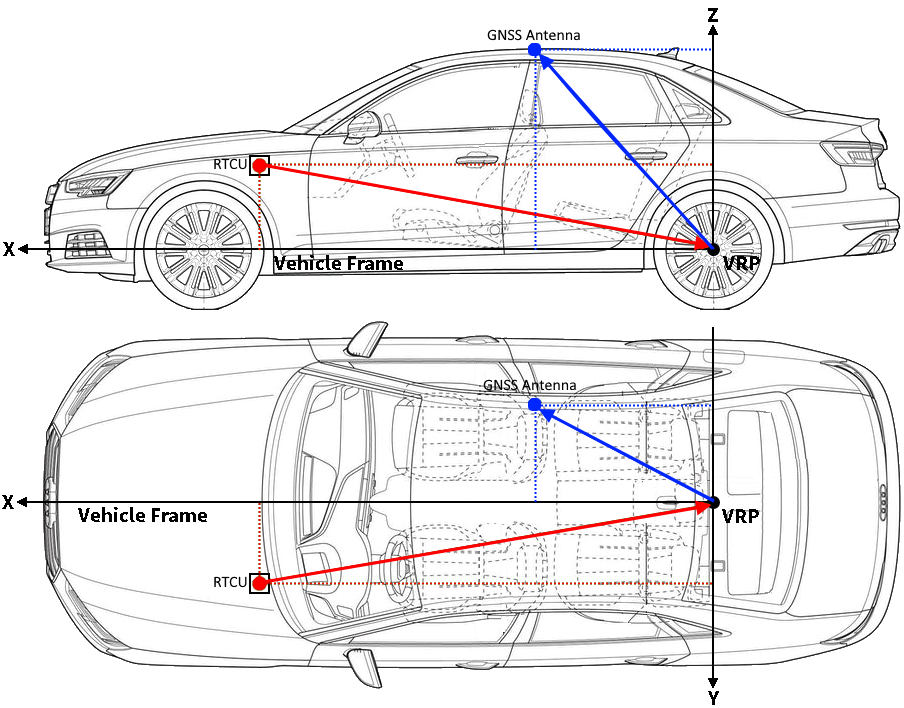
This configures one of the vectors which specify the location of the RTCU Device, the GNSS Antenna and the Vehicle Reference Point (VRP) in relation to each other.
If the RTCU device is placed at a significant distance from the GNSS Antenna or the VRP, then errors can be introduced in the navigation solution (particularly when the vehicle experiences high heading rate).
Setting the mount location of the GNSS Antenna and the RTCU device, will compensate for these errors.
The vectors are located in the Vehicle Frame, originating from the VRP or the RTCU device.
The VRP is the nominal point at which some motion constraints inherent to ground based vehicles are applied.
For automotive platforms, the VRP is defined as the center of the vehicle rear axle.
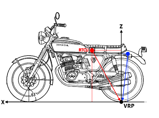
For bike platforms, the VRP is defined as the point where the wheel touches the ground. If the RTCU device is mounted on the handle bar, the VRP will be where the front wheel touches the ground, and if the RTCU device is mounted on the bike frame the VRP will be where the back wheel touches the ground.
The Vehicle Frame is a right-handed 3D Cartesian frame connected to the vehicle.
The x-axis points towards the front of the vehicle, the y-axis points towards the left of the vehicle and the z-axis completes the right-handed reference system by pointing up.
This illustrates how to determine the vectors on automotive platforms:
And for bike platforms:
Input:
type: SINT
The vector to change:
0 |
VRP to GNSS antenna |
1 |
VRP to RTCU device |
2 |
RTCU device to GNSS antenna |
3 |
RTCU device to VRP |
x: INT
The x-axis of the vector in cm.
y: INT
The y-axis of the vector in cm.
z: INT
The z-axis of the vector in cm.
Returns:
1 |
- Success |
0 |
- Unsupported |
-1 |
- Invalid input. |
-2 |
- Generic error |
-3 |
- GNSS power is OFF |
Declaration:
FUNCTION gnssDRMountSetup : INT;
VAR_INPUT
x : INT;
y : INT;
z : INT;
type : SINT;
END_VAR;
Example:
INCLUDE rtcu.inc
PROGRAM test;
BEGIN
...
// Specify vector from reference point to GNSS antenna
gnssDRMountSetup(type := 0, x := 100, y := 0, z := 150);
// Specify vector from reference point to RTCU device
gnssDRMountSetup(type := 1, x := -20, y := -50, z := 20);
...
END;
END_PROGRAM;